Led Chaser Circuit Diagram Using 4017 And 555 Led-chaser-usi
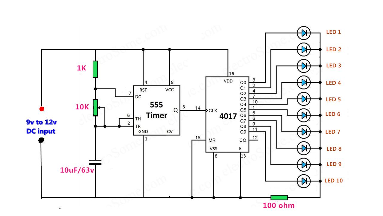
Led chaser using a cmos 4017 and a 555 Circuit led 4017 chaser 555 ic running light using make Chaser led 555 cd4017 using timer circuit circular circuits projects electronics diagram explanation working hackster
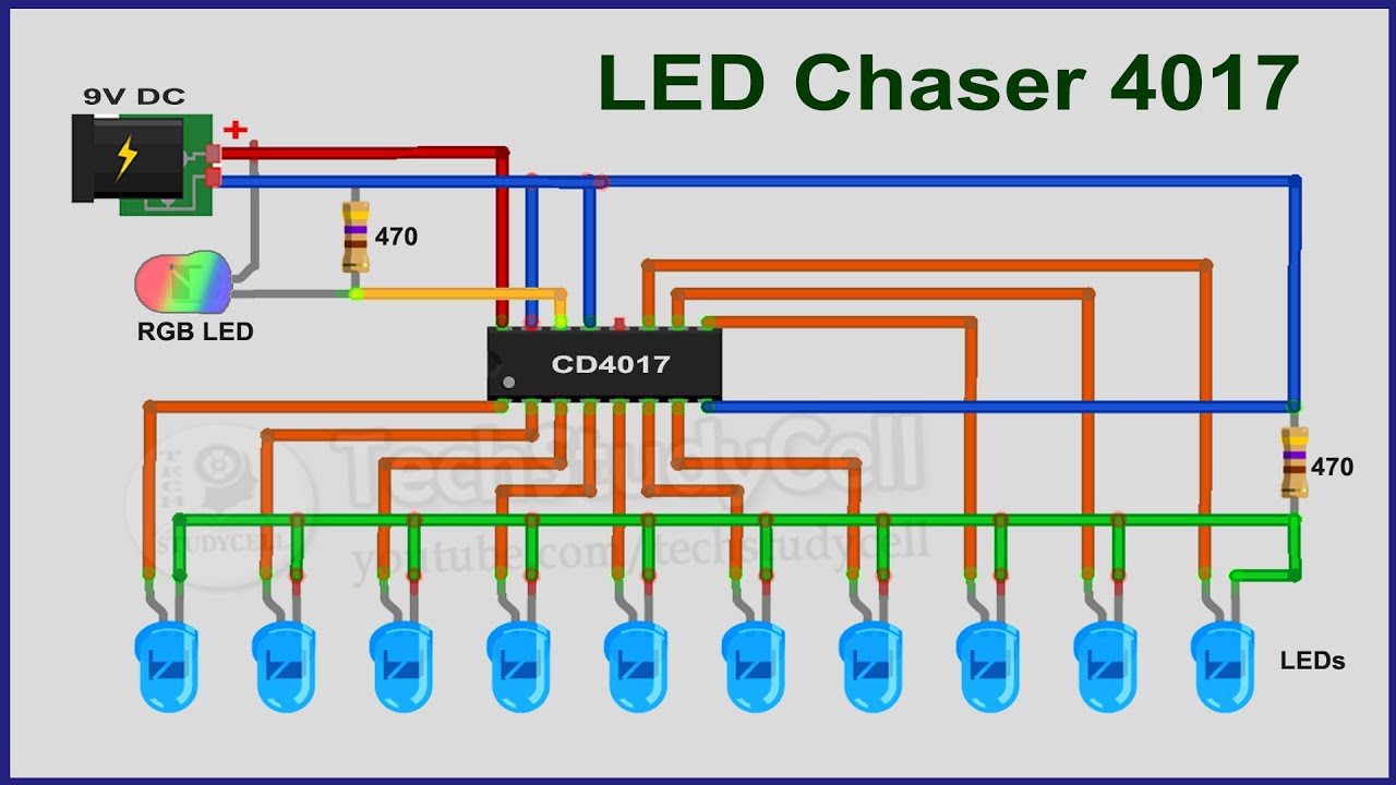
4017 LED chaser Circuit Diagram with RGB LED - 4017 Projects 2020
Led chaser using 4017 counter and 555 timer Led chaser circuit 4017 using 555 diagram cmos light seekic ic 4017 and 555 circuit diagram
Diagram 4017 555 led chaser capacitor timer wiring using counter circuit motor run start ic phase
Led chaser circuit using ic 4017 and 555Led chaser by ic 4017 + ic 555 |electronics projects (project help) led chaser with 555 and 4017 flashing too fast (comments10 channel chaser led light using ic 555 and cd4017 // method-1.
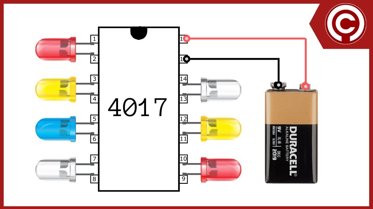
How to make led chaser circuit with only 4017 icLed chaser using a cmos 4017 and a 555 11+ led chaser circuit using 4017 and 555Led chaser using 555 timer and 4017 counter.

4017 chaser led 555 pcb using counter timer bottom ic top
Led chaser using 4017 counter and 555 timerLed circuit chaser 4017 555 ic running lights eleccircuit using light diagram rider knight circuits timer circle project variable which Led chaser circuit diagram using ic 555 and cd 4017Led chaser circuit with pcb layout.
Led chaser circuit / sequential led flasher using 4017 ic and 555 timerSimple led chaser circuit Led chaser circuit using 4017 and 555 timer icLeds chasing circuit using 4017 ic and 555 timer "kit".
4017 led 555 ic chaser circuit circuits projects sequencer schematic relay counter simple mini pcb running decade lights layout sensor
Livra metal îndărătnic led chaser circuit using 4017 and 555 shuraba4017 555 leds timer chasing 4017 led chaser only4017 led chaser circuit diagram with rgb led.
Chaser lights circuit diagramLed-chaser-using-555-timer-and-4017-ic-working ⋆ gianghm 4017 chaser rgbLed chaser circuit with pcb layout.

Circular led chaser using 555 timer & cd4017
How to make led chaser circuitLed circuit 4017 cd4017 running chaser ic using ne555 diagram lights eleccircuit circuits counter datasheet way two decade timer pinout 4017 555 circuit diagram sequencer chaserCircuit cd4017 ic led chaser simple diagram pcb timer.
10 channel simple led chaser or running light using 555 and 4017 ic4017 chaser ic circuits components rider Led chaser circuit 4017 using 555 diagram cmos light seekic icCd4017 chaser 555.

4017 led chaser 555 ic circuit using circuits sine wave datasheet oscillator cd4017 running lights pcb pinout constant frequency low
Led chaser circuit by ic 4017 + ic 555 -eleccircuit.com4017 chaser ic schematic rgb pcb wiring Led chaser using 4017 counter and 555 timerLed chaser with only 4017.
Led chaser using cd 40174017 555 chaser timer pcb ic Led chaser using 555 timer and 4017 counterDiytechstudio: led chaser or sequencer using 555 & 4017.

4017 led chaser circuit diagram with rgb led
4017 led chaser using cd circuit circuits diagram flasher related simple circuitdiagram4017 and 555 circuit diagram Led chaser using 555 timer and 4017 counter.
.